Home My projects Packet Tracer Projects

Packet Tracer Projects

Here you can find my deep dives into networking and videos from my packet tracer labs. There are videos to show off system functionality and packet functionality.

Restricted three tier topology

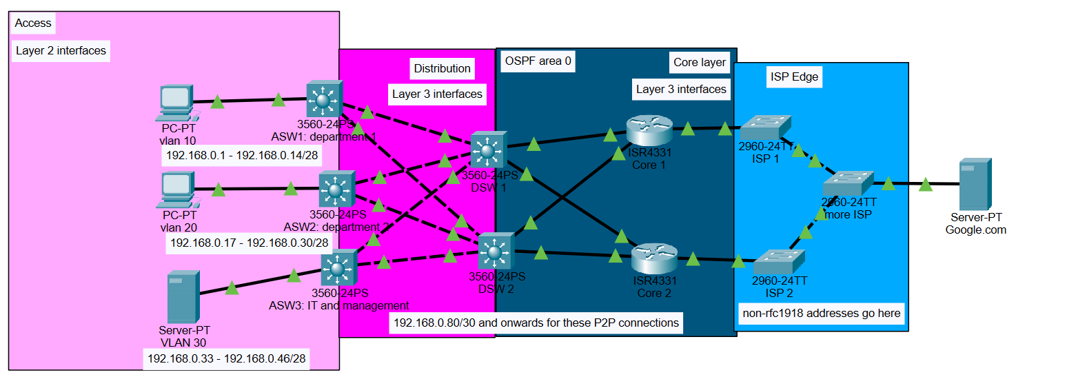
This topology is a mostly text book version of a three tier architecture. While it lacks a redundant distribution and core layer, this does not take away from its scalability. I designed this network in a way that demonstrates real world hardware constraints. The reason I did this was because in my own personal homelab, I deal with restraints like this constantly. Not every business has massive IT budgets and as an aspiring network engineer, this is a reality one must confront. I used single PCs to represent multiple hosts.

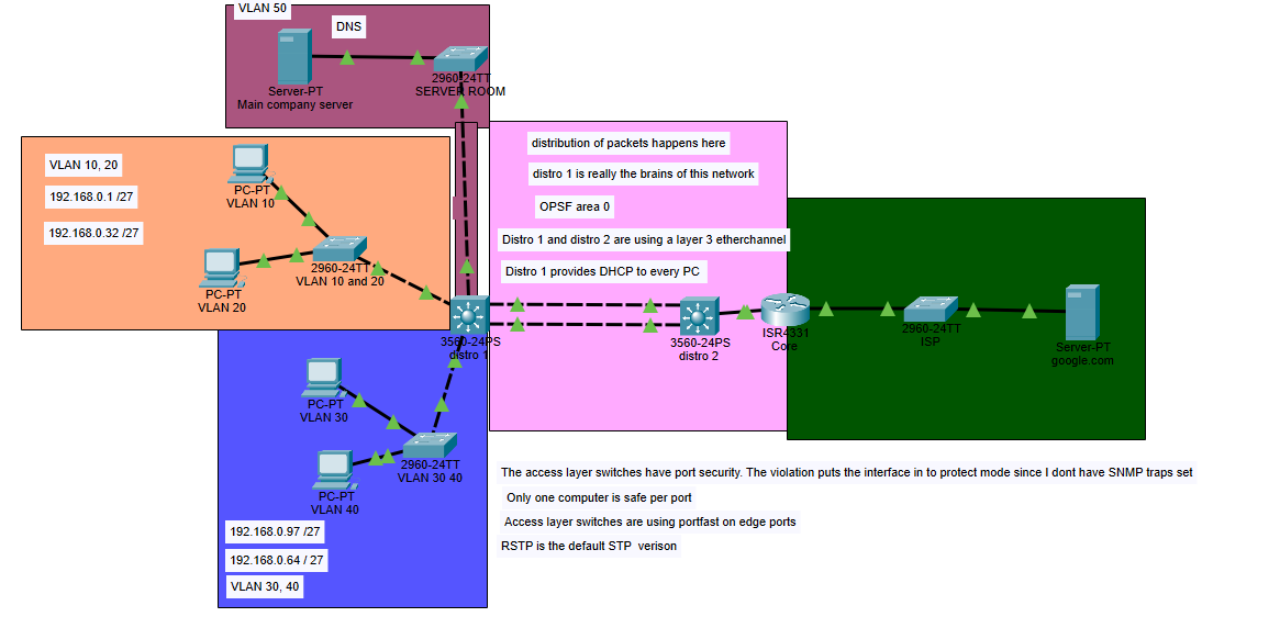
Each VLAN can support 30 hosts which seems like a reasonable number to allow for later expansion. I decided to use a /27 mask because it should last a small business quite a while. These VLANs also represent different departments of the business and it's also good practice to segment these aspects of the business from each other However, there are plenty of downsides to this infrastructure. One of the biggest issue is that the distribution layer has no node to node redundancy. Normally, we would want our access layer switches to connect to more than one distribution switch, however, there is no such privilege afforded in this situation. So, the next best thing we can do is give redundancy to links using EtherChannel. So an L3 EtherChannel is administered.

I choose an L3 EtherChannel over an L2 EtherChannel because we want to keep the core the "dumbest" layer in the network. L3 allows us to put more L3 responsibilites on the distribution switch. More importantly, in the case of a link failure, we get to converge/ recover much faster than an L2 EtherChannel because the links still need to account for spanning tree protocol. An L3 EtherChannel also allows for better load balancing configurations such as using ECMP via OSPF. Lastly, an L3 EtherChannel allows us to limit the size of broadcast domains, which should give us slightly increased security, increased core performance, and a less noisy network.

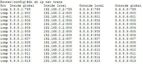
There are some services that run on the network. Mainly, DHCP, DNS, and PAT. In order to take some load off the distribution layer I opted to give a server the job of running DHCP and DNS. I did a provide a video of DNS working as well. Its function in the network is quite simple. It's there to map domain names to IP addresses. These are extensively used in business networks, so much so that you would have a hard time not finding a network with some kind of DNS on it. Technically speaking, the distribution layer 1 switch can handle these DNS requests as it has DNS server functionality, but the distribution layer is already doing a quite a few jobs. Switches only have so much processing power and memory, and with only one node doing so much there needs to be another system that takes this load off. This same logic applies to DHCP. DHCP does get centralized into the server. This is best practice regardless because DHCP likes to be centralized.

Physical Homelab Setup Physical Homelab Setup

Highly Available Routed Access Design Network

This network uses OSPF, VLANs, DNS, and DHCP. The more important aspect of it is the design. This is known as a Routed Access network. This means that Access switches are no longer just layer 2. They gain layer 3 interfaces and become active in the OSPF routing process. This has many advantages, such as load balancing at the first hop of the network, fast convergence times if a link goes down, and even greater control of how traffic is handled. It's also not much more difficult to expand to. It's just more costly because of the additional Ethernet you need to purchase. VLANs are used to control broadcast traffic, and ACLs are used to prevent unicast traffic from entering and possibly causing issues in other VLANs. This network is designed to be very redundant; however, there is one glaring single point of failure. It's the host devices. If the immediate next hop for the switches goes down, then that area of the network goes down too.

The access network is doing a bit more for the network. We still use VLANs because it's not only just a good idea in general, but if we want to utilize our switches more, then VLANs make this possible. If we need to add another department on the same floor of a building ad hoc, then we can simply make them a new VLAN, and nothing will interfere with the preexisting traffic. Adding a new department becomes easy because we just have to separate traffic and give them an SVI for their gateway of last resort. The simplicity in the management of access design makes adding and removing things like this very easy.

The Access - Distribution layer section is actually based on spine-leaf architecture used in data centers. This means each leaf is connected to each spine to create a half-mesh network. In this design, we are effectively trying to increase redundancy where it needs to be while not forwarding traffic where it doesn't need to be. In other words, there is no east - west traffic here, only north - south. This is why we don't connect the access switches to each other.

Once again, the distribution layer is doing a lot of heavy lifting here. It's running the OSPF services, connecting each host network to the servers, and it's where most of the routing decisions are made. VLANs do not run across L3 links, but packets can and will still be routed across these links and appropriately tagged at the access switches. This is a cause for concern for security issues, so an ACL is used to block unicast messages.

The core layer is basically running nothing. This layer is meant to be very "dumb" and fast. We want only the bare minimum processes running here. Each router is using PAT, and each one is connecting to a separate ISP, and each router is routing via OSPF as well.

To summarize key points:

  • Routed Access design is used for fast convergence and load balancing on the first hop
  • VLANs are used to control broadcast traffic each access switch
  • ACLs control traffic between LANs via blocking unwanted unicast traffic
  • Distribution layer handles OSPF, routing decisions, and connects host networks to servers
  • Core layer is kept intentionally "dumb and fast" with only PAT and OSPF, plus separate ISP connections per router
  • Host devices are a single point of failure. If an access switch's immediate uplink fails, that entire switch domain goes down

In conclusion, we can observe that routed access design allows for a robust and dynamic network not only in operation but in management as well.

Physical Homelab Setup

This is the process that DNS uses to inform hosts about the IP address of a domain name. The ICMP process shows off how OSPF load balances across the network.

This is the DORA exchange process that DHCP uses to assign IP addresses. The IP helper command was administered on the SVIs in order to facilitate the transmission of these broadcast messages.

Powered in my personal homelab